
← Back to “Processing sections & scripts”
Preparation — scan-pattern design
Plan the acquisition by defining and managing the probe coordinate grids (scan patterns) used by 4D-STEM. These write project-wide STAR files that the import step later reads.
| # | Title | What it does |
|---|---|---|
| 40 | Scan Pattern Generator | Creates a scan pattern defining the probe coordinates for an acquisition and writes it to a STAR file. |
| 42 | Scan Pattern Inventory | Lists the scan patterns already available in the project's STAR files. |
| 45 | Scan Pattern Translator | Converts between the TVIPS three-file scan-generator format and a STAR file, in either direction. |
| 60 | Grab central positions | Extracts the 30 most central probe positions from a pattern for quick centered tests. |
.star files in the project's STARFILES/ directory. Each script's ? help button opens its entry below. (These scripts show an interactive plot only when Show plot of scan positions is on — no plot image is saved to disk.)
40 — Scan Pattern Generator
Purpose
Generates a fresh probe scan pattern — the ordered list of X/Y probe coordinates a 4D-STEM acquisition will visit — purely computationally from a chosen geometry, and writes it to a STAR file in STARFILES/. This is the primary "design a scan" tool: pick a pattern type and a number of positions, and it produces the coordinate list that later drives the scan generator and indexes the recorded diffraction stack.
Parameters
| Parameter | Role |
|---|---|
ScanMode | The pattern geometry (drop-down) — see the algorithm for the full list. |
ProbePositions | Total number of probe positions to generate. |
ProbePositionsPlot | How many positions to draw in the plot (0 = all). |
ProbePositionsHorizontal, ProbePositionsDosefrac | Horizontal count and repetitions, used only by the hexagonal dose-fractionation modes. |
snakeoffset | Row offset for the Snake-Offset pattern. |
makeMultipleScanPositions | Write the whole pattern this many times (dose-fractionated), each repeat given a tiny jitter. |
scan_showplot, scan_y_down | Show the interactive scatter plot; invert its Y axis. |
ScanPatternSTAR | The output STAR filename (written into STARFILES/). |
Algorithm
- Writes the STAR header (
_scan_mode,_probe_positions, theloop_columns). - Dispatches on
ScanModeto a dedicated generator: Square, SquarePattern-DoseFrac, Snake, Snake-Offset, Spiral, HexPattern, HexDoseFracRound / HexDoseFracSquare, Fermat, Fermat-Ysort, Random, and Develop_1…5. - Rescales X and Y independently to the scan-generator integer range (roughly −6500…6500) as int16 — the STAR file stores hardware deflection coordinates, not Ångström distances.
- Repeats the pattern
makeMultipleScanPositionstimes with a running position offset (and a tiny jitter on repeats), then optionally shows the scatter plot.
Results
Images: an interactive scatter plot only if Show plot is on (no PNG is saved).
Data written: the STAR file STARFILES/<ScanPatternSTAR> (one row per probe position); the results file registers the STAR file and records the final ProbePositions count.
42 — Scan Pattern Inventory
Purpose
A read-only bookkeeping tool. It scans the STARFILES/ directory and lists every existing scan-pattern STAR file with its scan mode and number of probe positions, so you can see at a glance which patterns are already available.
Parameters
This script inherits the standard scan-parameter list in its GUI, but its logic uses none of them to select or filter — it always lists all .star files. There are no effective inputs.
Algorithm
- Ensures
STARFILES/exists. - For each
.starfile, reads until it finds_scan_modeand_probe_positions, then records that file's mode and position count (malformed files are skipped).
Results
Images: none.
Data written: nothing on disk is changed. It prints one line per pattern to the log and registers each STAR file as an "important" result (labelled with its mode and position count), so the inventory appears prominently in the Results panel.
45 — Scan Pattern Translator
Purpose
Converts scan patterns between the microscope's TVIPS scan-generator format (plain-text _x/_y/prescan integer lists) and 4d's STAR format, in either direction. This bridges externally acquired or scan-generator-native patterns with 4d's STAR-based pipeline, including handling of "prescan" (dummy lead-in) positions.
Parameters
| Parameter | Role |
|---|---|
ScanPatternTranslate | Direction: 0 = do nothing, 1 = TVIPS → STAR, 2 = STAR → TVIPS. |
ScanPatternSTAR | The STAR file read (dir 2) or written (dir 1). |
ScanPatternTVIPS | Base name of the TVIPS triple (<name>_x.txt, _y.txt, _prescan.txt). |
ScanPattern_prescan | Whether prescan (dummy lead-in) positions are expected/created. |
ProbePositionsZeroStart | Number of dummy positions inserted before the real scan. |
StepSize, ScanMode | Step size (Å) and scan mode carried through the STAR header. |
ProbePositionsPlot, scan_showplot, scan_y_down | Plot controls. |
Algorithm
- TVIPS → STAR: loads the X/Y integer arrays (the
_prescanvariants when flagged), drops the blank lead-in dummies (keeping only flagged real positions), and writes the STAR file. - STAR → TVIPS: parses the STAR header and rows and writes
<base>_x.txt/_y.txt; when prescan is on it prepends synthetic lead-in positions (linear extrapolation), uses the_prescanfilenames, and writes a companion flag file (0 for each dummy, 1 for each real position). - Optionally shows the resulting scatter plot.
Results
Images: an interactive plot only if Show plot is on.
Data written: the STAR file (dir 1) or the TVIPS text files <base>_x[_prescan].txt, _y[_prescan].txt and _prescan.txt (dir 2); all written files are registered to the Results panel.
60 — Grab central positions
Purpose
Reads an existing scan-pattern STAR file, computes the pattern's centroid, and extracts the 30 probe positions closest to that centre into a new, smaller STAR file. This gives a compact "central subset" pattern — handy for quick tests, alignment, or focusing on the centre of the field without running the full scan.
Parameters
| Parameter | Role |
|---|---|
ScanPatternSTAR | The input STAR file (in STARFILES/). |
imagenumber, imagename, comment, tempkeep | Standard image/utility fields (not used by the logic). |
The count — 30 positions — is fixed.
Algorithm
- Parses the STAR file's header and position rows.
- Computes the centroid (mean X, mean Y).
- Sorts all positions by squared distance to the centroid and keeps the closest 30 (or all, if fewer).
- Writes the subset, re-indexed, to a new STAR file.
Results
Images: none.
Data written: a new STAR file STARFILES/<name>_centerpositions.star with the up-to-30 most central positions; both the original and the new file are registered to the Results panel.
ScanInspect — visualise a scan pattern
ScanInspect is an interactive viewer for scan patterns, reached
from the Planning tab (4D-STEM project mode). A scan pattern is
the list of probe positions a 4D-STEM acquisition visits, stored as a
.star file by the Scan Pattern
Generator. ScanInspect lets you load such a file and see the pattern
before you use it — to confirm its geometry, spacing, coverage, scan order, and
the coordinate convention are what you intend.
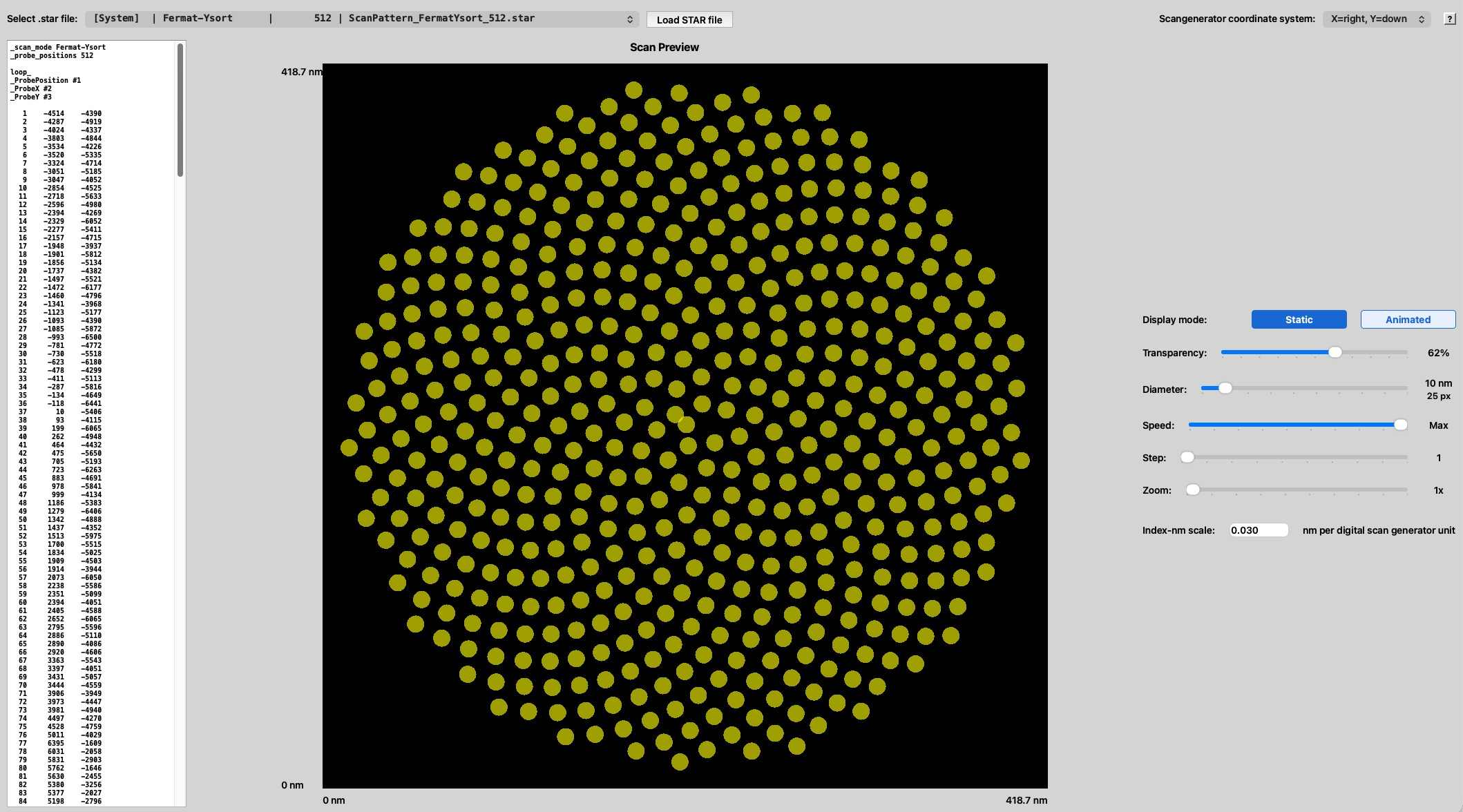
It loads a scan-position .star file and draws every probe position as
a dot on a canvas. The numbered markers on the screenshot below point to each
control; the legend that follows explains them, and the small ?
button at the far top-right of the window opens this page.
 1
2
3
4
5
6
7
8
9
10
11
1
2
3
4
5
6
7
8
9
10
11
| # | Control | What it is and does |
|---|---|---|
| 1 | Select .star file / Load STAR file | Choose a scan-position .star file (the drop-down lists the patterns in the project's STARFILES/) and press Load STAR file to display it. |
| 2 | Scangenerator coordinate system | Whether the file's Y axis points down (X=right, Y=down) or up (X=right, Y=up), matching your scan generator so the preview is oriented correctly. |
| 3 | File preview | A text panel showing the loaded file's first lines — the header (_scan_mode, _probe_positions) and the numbered X Y position list. |
| 4 | Scan Preview canvas | Every probe position drawn as a dot, with a nanometre scale on both axes. Drag to pan; scroll or pinch to zoom. |
| 5 | Display mode | Static shows the whole pattern at once; Animated draws the positions in acquisition order to reveal the scan path. |
| 6 | Transparency | Dot opacity — lower it to see overlapping dots in dense patterns. |
| 7 | Diameter | Dot size, in nm (with a pixel read-out). Set it near the intended probe size to judge overlap. |
| 8 | Speed | Animation rate (up to Max) when Display mode is Animated. |
| 9 | Step | How many positions are added per animation step. |
| 10 | Zoom | Magnify the preview (1–100×); also available with scroll/pinch on the canvas. |
| 11 | Index–nm scale | Nanometres per digital scan-generator unit — calibrates the axes so the pattern is shown at true physical scale. |
Step-by-step
- Open ScanInspect from the Planning tab.
- Pick a pattern (1): choose a
.starfile from the drop-down and press Load STAR file. The file preview (3) and the canvas (4) fill in. - Set the coordinate convention (2) to match your scan generator, so up/down is correct.
- Set the physical scale (11): enter the nm-per-scan-unit value so the axes read in true nanometres.
- Inspect the geometry (4): pan and zoom (10) the canvas to check spacing, coverage and shape; adjust Diameter (7) and Transparency (6) to judge how much neighbouring probes overlap.
- Check the scan order: switch Display mode to Animated (5) and use Speed (8) and Step (9) to watch the positions appear in acquisition order — useful to confirm the fly-back/serpentine path is what you expect.
- Accept or revise: if the pattern is right, use it for acquisition; if not, edit it with the Scan Pattern Generator and reload.
.star file. Use the Scan Pattern Generator to create or change patterns.